A wide variety of programs is available to do further analysis of the data. Exactly which ones you will need depends on the nature of your observations. To see the latest list of symbols related to spectroscopy, enter
or consult Chapter 13 of the  ook
ook ook for a less current, but paper, copy of the list.
The subject of finding and removing the continuum (aka spectral baseline) was discussed in §8.3 above. In the image domain, task IMLIN may be used to remove polynomial baselines using the same spectral channels throughout the cube. The task XBASL can be used to remove baselines in an interactive (hence position-dependent) fashion. Be aware, however, that if you have made an error in the calibration, this has most likely caused slopes in amplitude and phase. Therefore, it is generally better to track down the error and correct it than to decide (arbitrarily) to take out slopes in (Cleaned ?) image amplitude. Task SQASH may also be used to sum or average planes in a cube, which provides, among other things, a simple but crude way to determine a continuum image which can then be subtracted from the cube by COMB.
Smoothing and blanking are important for almost all analysis programs. CONVL works on cubes and does a spatial smoothing (on position-position-velocity cubes). CONVL will use the CG table to smooth all image planes to the same spatial resolution. This is preferable to forcing a resolution with BMAJ since it smooths the residuals as well as the components. Using all the defaults in XSMTH performs a Hanning smoothing in velocity (on transposed velocity-position-position cubes) and can be used to do other kinds of smoothing as well. This is not just useful for bringing out weak extended signals. Smoothed images can also assist in determining the boundaries of sources to set windows for subsequent spectral analysis. For example, the smoothed cube could be used to set the CLIP limits in task COMB to be applied to the unsmoothed cube.
In fact, finding all regions of significant line signal may be difficult in large image cubes. The task SERCH offers an algorithm by Juan Uson to find line signals which match specified line widths and exceed a specified signal-to-noise ratio. Histograms may be plotted or printed and a S/N hyper-cube may be written.
The task BLANK offers a variety of algorithms for “blanking” out regions of bad data or source-free regions in spectral-line cubes. It has an interactive mode, which allows you to indicate with the cursor on the TV what are “good” regions. Set everything but the image name to default values, use OPCODE ’TVCU’ C R and type GO BLANK C R. Then just follow the instructions, pushing button A to lay out the polygon and button D followed by C R to go to the next image. If marking “bad” regions is easier, set DOINV TRUE C R before running BLANK. A less subjective way is to use BLANK with OPCODE = IN2C. Blanking is done based on the pixel values in a second cube, usually a smoothed version of the original cube. OPCODE=’BOX’ simply blanks inside or outside a list of circular or rectangular boxes. Task RMSD can be used to blank an image based on its rms in a window surrounding each pixel. It can also be used to compute images of rms using robust, histogram, or median-absolute-deviation (“MAD”) methods.
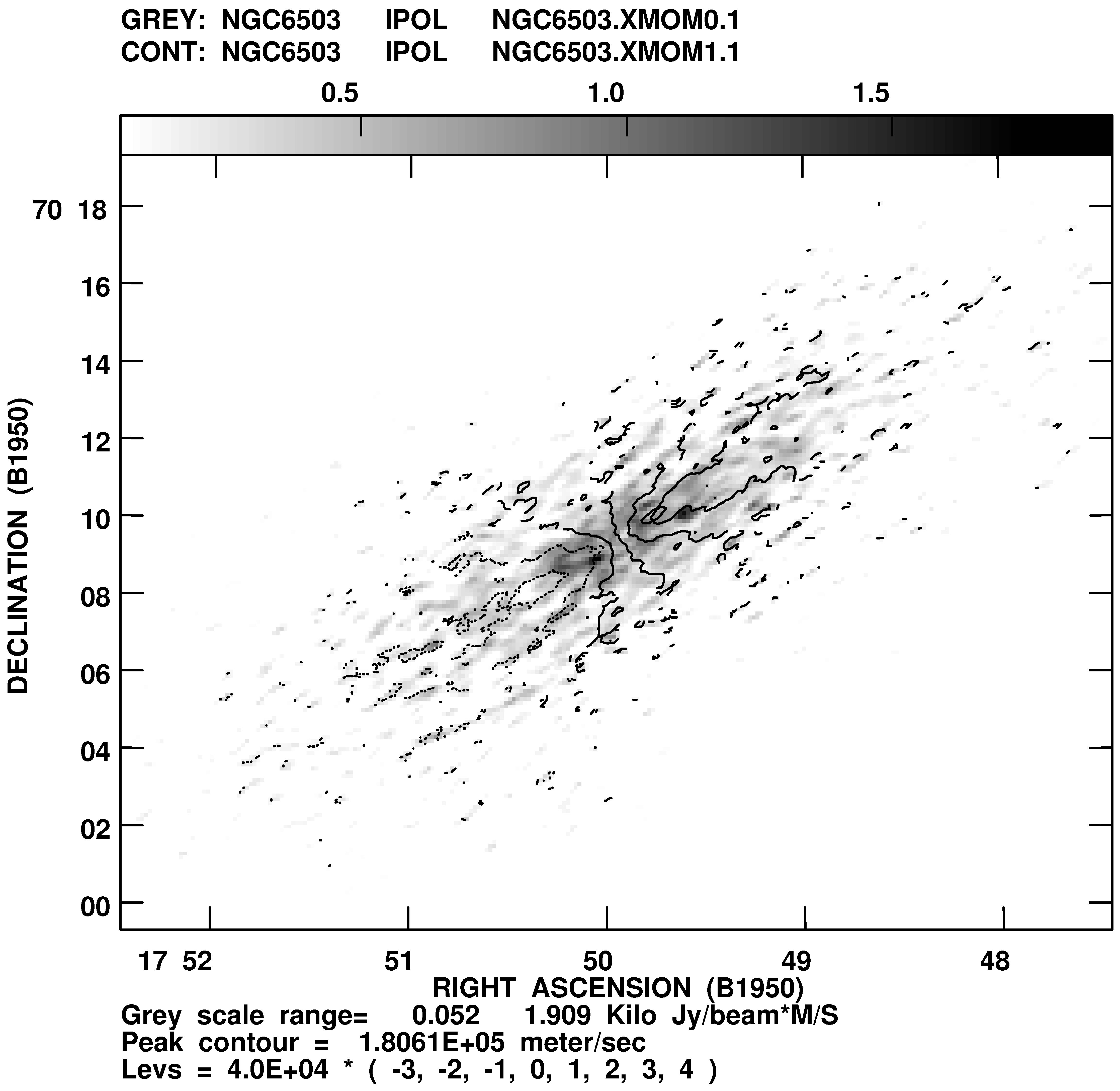
The blanked cubes can be used to calculate integral profiles with BLSUM and to calculate moments 0 to 3 of the profiles with XMOM. Thus, the 0-moment image will be the integral under the profile (e.g., total HI), the first moment is the velocity field, etc. OPTYPE=’MAX’ in XMOM will select the peak brightness on each row and make images of it and its coordinate. A comparison of the two types of output can be very illuminating. Task MOMNT does the smoothing, blanking and calculating of moments all in one run. This is very easy to use, but can be dangerous since you don’t see what is going on. A display of the 0th and 1st moment images computed by XMOM is shown in Figure 8.4.
Moment images (or any other 2 or 3 images) may be combined in a display in which one image controls intensity, a
second image controls hue (color), and a third optional image controls saturation (color richness or purity, done by
varying the ratio of white to pure color). In the days of powerful television display devices, this display could
be done at truly interactive speeds in the display hardware. Today, most workstations are capable
of displaying full color images and the 


 display program supports them. The verb TVHUEINT
will display the two specified TV channels using one as the intensity and the other as hue; see §6.4.7
task HUINT may also be used with either full-color TV displays. This task offers a small menu of
interactive options to enhance the images and otherwise control the display in manners essentially the
same as the verb. It however offers the option to write out an image cube having RGB as its third axis.
It can also write an image of the 3-color step wedge. These images may then be processed with the
usual display tasks such as KNTR and rendered in PostScript by LWPLA. task TVHUI may also be
used with either full or pseudo color TV displays. This task also offers a small menu of interactive
options to enhance the images and otherwise control the display. It also offers the option to write out
an image cube having RGB as its third axis and using much greater mathematical accuracy than is
allowed in the TV display. Procedure TV3LOD loads an RGB cube to the TV display with appropriate
colors.
display program supports them. The verb TVHUEINT
will display the two specified TV channels using one as the intensity and the other as hue; see §6.4.7
task HUINT may also be used with either full-color TV displays. This task offers a small menu of
interactive options to enhance the images and otherwise control the display in manners essentially the
same as the verb. It however offers the option to write out an image cube having RGB as its third axis.
It can also write an image of the 3-color step wedge. These images may then be processed with the
usual display tasks such as KNTR and rendered in PostScript by LWPLA. task TVHUI may also be
used with either full or pseudo color TV displays. This task also offers a small menu of interactive
options to enhance the images and otherwise control the display. It also offers the option to write out
an image cube having RGB as its third axis and using much greater mathematical accuracy than is
allowed in the TV display. Procedure TV3LOD loads an RGB cube to the TV display with appropriate
colors.
RGBMP computes “integral” images another way — as three weighted sums representing the low, center, and high velocity parts of the cube. Like TVHUI, RGBMP writes its results as a cube with RGB as the third axis. Task TVRGB can display these outputs (or any other RGB cube or any three image planes), using one image plane to control the red image, one to control green, and one to control blue. It works on real TV displays and full-color workstations and, using an algorithm to minimize the loss of color information, on pseudo-color workstations. Like TVHUI, it offers a small menu of interactive enhancement options. TVRGB can write 24-bit color PostScript files beginning with the 15JAN96 release. TVCPS is another way to capture the displays generated by TVHUI and TVRGB to send to color PostScript printers.
If you prefer to fit Gaussians instead of calculating moments, the program XGAUS can be used. First, it is a good idea to become acquainted with your data cube. A highly interactive task called TVSPC2 can let you examine the spectra from one or two transposed cubes at positions selected from an image plane, all on the TV display. The image plane should be some image representing the full field, such as moment-zero or, in polarization, the I polarization image. This task can also display another, non-transposed cube with the displayed plane selected from the displayed spectra. Another highly interactive task called TVIEW3 lets you examine cubes simultaneously in all 3 transpositions. In earlier releases, use XPLOT first to look at (a sample of) the profiles, before you do any Gaussian fitting. XGAUSS offers a non-interactive mode, but it is frequently unstable and depends on the fit channels and the initial guesses being virtually independent of position. Therefore, in most cases, it is preferable to use the interactive mode, so that you can see what is happening, but be aware that it might be rather time-consuming. XGAUS prepares a table of solutions which can be edited in various ways after all pixels have been fit once. Images of the fit parameters and uncertainties and of the rms of the residual spectra are examined during the editing process and are written out only after you are happy with the results. The task may be re-started with the same table as often as needed. This allows for processing limited regions of the celestial coordinates that have similar spectra, for changing the number of Gaussians fit, and for fitting weaker signals later in the process.
RMFIT is used to fit rotation measures to Q and U spectral cubes, using the cube of Faraday rotation output by FARS
to provide initial guesses. It is far more capable than the Faraday rotation synthesis in distinguishing
multiple components in the rotation measure. ZEMAN fits Zeeman splitting to spectral cubes of I and V
polarization. It can fit the line directly or it can fit the individual Gaussians found by XGAUS individually.
The latter allows multiple magnetic-field values to be found in the same direction. See Memo
1184 for
a detailed description of these tasks.
Two more similar tasks have appeared to handle the different mathematics required by absorption-line
image cubes. When optical depths become significant, the noise in optical depth becomes a strong
function of the optical depth, so the fitting is done in the observed absorption spectra rather than in
optical depth even though it is the optical depth which is treated as Gaussian. These tasks, AGAUS and
ZAMAN function very much like the tasks for emission-line cubes except that initial guesses are set on a
plot of the optical depth spectrum in AGAUS and for details of the mathematics. See Memo
1225 .
Three tasks support the XG, ZE, and RM tables produced by the above family of tasks. XG2PL plots spectra from XG and/or ZE tables, while RM2PL performs a similar function for tables from RMFIT. Task XG2XG copies an XG or ZE table to a new table with a different maximum number of Gaussians.
The cube can be rotated with OGEOM (if the α – δ pixels are square), e.g., to align one of the axes with the major axis of a galaxy. If the pixels are not square, use OHGEO to re-grid the image instead. A single profile can be produced from these images with SLICE, then plotted using TKSLICE,TVSLICE, or SL2PL (see §6.5.2, §6.4.8, §6.3.2.2, and Figure 6.6). PLCUB, PLROW and XPLOT are convenient programs for displaying multiple individual spectral profiles after the cubes have been transposed.
To compute and display spectral profiles summed over regions in the two angular coordinates, use ISPEC for
circular and/or rectangular regions and BLSUM for irregular regions set interactively using the TV display and
cursor. Both tasks print their results; both BLSUM and ISPEC make standard plot files, and BLSUM can also
make a printer plot. Note that both tasks sum over areas in the first two axes and plot that as a function of position
on the third axis, no matter what the three axes actually represent. This suggests a variety of interesting
possibilities, such as time functions or line integrals versus position in the source. Both tasks can write the results as
slice extension files which may then be printed, plotted and Gaussian fit in a variety of ways. ISPEC can plot the
spectral derivative of the profile it has computed, which is of interest in Zeeman splitting experiments. Task
RSPEC is similar to ISPEC except that it plots the rms rather than the data. RSPEC has options to write
out a signal-to-noise image and/or a text file of channel weights as well. In 31DEC26, task CSPEC is
similar to ISPEC and RSPEC except that it computes two spectra (actual or rms) and then plots them
overlapped or shifted vertically or mathematically combined. It can print to a text file in a variety of useful
formats.
In 31DEC25, task IM2TX writes out a text file containing a one-dimensional array from the sum, average, or rms from
an N - 1 dimensional region of the image cube. Task TX2IM can read such text files back into . Such
one-dimensional images play well with SLICE and SLFIT.
Note that if all you require is a single spectral profile, it may be possible to use POSSM which works on the uv data directly. If the spectral profile is a function of position within a well-resolved source, then you will have to go to the image plane.
GAL fits models of galaxy rotation to images of the predominant velocity (e.g., the first moment images written by XMOM, XGAUS, or MOMNT). It accepts a second input image to be used as weights for the first input image; it is common practice to use a the zero’th moment image for this. Plots may be produced. The task MODVF creates a model velocity field based on a user provided model for the rotation curve, orientation, and warping of the plane.
A much more powerful, but tricky to use, task named CUBIT was developed by Judith Irwin and contributed to
6 .
This task fits a galaxy rotation and emitter (usually HI) distribution to the full data cube. It uses dynamic memory
and so can work on any reasonable size cube. It is much more likely to work if the cube has been very carefully
BLANKed and if you approach it with patience. Make the best initial guesses for all the parameters that you can.
Then fit for one parameter at a time until you begin to get a reasonable result. Then allow the task to fit all of the
parameters at once. And finally, check the fits going through the galaxy in halves or quadrants. But first, study
EXPLAIN CUBIT C R in detail. The results from this task are worth the trouble to get it to work on your
data.